Hantek DSO8102E Digital Oscilloscope LCD USB PC Recorder DMM Spectrum Analyzer
Frequency Counter Arbitrary Waveform Generator
Overview:
* Six in one: Oscilloscope/Recorder/DMM/ Spectrum Analyzer/Frequency Counter/Arbitrary Waveform generator.
* IP-51 rated for dust, drip and shake proof to withstand harsh environments.
* Large fuse confirms to European Safety Standard.
* Battery indicator with easy-changed connect points. Selectable 18650 battery box for matching 18650 battery by yourself.
* Anti-theft lock hole, tripod fixed hole, hang rope, FLASH light that can be used in darkness.
* Replaceable BNC safety joints, and additional one set of joints.
* High bandwidth 70MHz-200MHz Oscilloscope, 1GSa/s sample rate, 2M Memory depth.
* 25Mz Arb. Waveform Generator, 200 Mesa/s DDS, 12 bit vertical resolution, easy for simulating transducer
* 6000 Counts DMM, AC/DC voltage, AC/DC current, resistance, break, capacitance, and diode function.
* FFT spectral analysis; Waveform Math: add, subtract, multiply and divide; X-Y mode; more than 20 automatic measurements; PASS/FAIL Check function, apply to engineering application.
* Abundant trigger function, double timebase sampling, easy to observe two waveforms in different frequency.
* Record and replay of more than 1000 waveforms.
* Large 5.6 inch TFT Color LCD Display; High Resolution(640*480)
* USB Host/Device 2.0 full-speed interface; support removable disk; WIFI/LAN Option, easy to control by PC or long-distance.
* Waveform data can be output in WORD,EXCEL, BMP, JPG as time and voltage.
Parameters:
Model
DSO8072E
DSO8102E
DSO8152E
DSO8202E
Acquisition
Sample Modes
Real-Time Sample
Acquisition Modes
Normal
Normal data only
Peak Detect
High-frequency and randon glith capture
Average
Wavefom Average, selectable 4,8,16,32,64,128
Inputs
Inputs Coupling
AC, DC, GND
Inputs Impendance
1M2% 20pF3pF
Probe Attenuation
1X, 10X
Supported Probe Attenuation Factor
1X, 10X, 100X, 1000X
Maximum Input Voltage
CAT I and CAT II: 300VRMS (10×), Installation Category;
CAT III: 150VRMS (1×)
Horizontal System
Sample Rate Range
1GS/s
Waveform Interpolation
(sin x)/x
Record Length
2M
SEC/DIV Range
4ns/div~2000s/div, in a 2, 4, 8 sequence
2ns/div~2000s/div, in a 2, 4, 8 sequence
Sample Rate and
Delay Time Accuracy
50ppm over any 1ms time interval
Scanning Speed Range
4ns/div to 8ns/div; (-8div x s/div) to 40ms;
20ns/div to 80s/div;(-8div×s/div) to 40ms;
200s/div to 40s/div;(-8div×s/div) to 400s;
2ns/div to10ns/div;(-4div×s/div) to 20ms;
Delta Time Measurement Accuracy
(Full Bandwidth)
Single-shot, Normal mode: (1 sample interval +100ppm × reading + 0.6ns);
>16 averages: (1 sample interval + 100ppm × reading + 0.4ns);
Sample interval = s/div ÷ 200
Vertical System
Vertical Resolution
8-bit resolution, all channel sampled simultaneously
Volts Range
2mV/div to 100V/div at input BNC
Bandwidth
70MHz
100MHz
150MHz
200MHz
Rise Time at BNC( typical)
5ns
3.5ns
2.3ns
1.8ns
Analog Bandwidth in
Normal and Average
modes at BNC or with probe,
DC Coupled
400V(100V/div-20V/div);
50V(10V/div-5V/div);
40V(2V/div-500mV/div);
2V(200mV/div-50mV/div);
400mV(20mV/div-2mV/div);
Math
+, -, *, /, FFT
FFT
Windows: Hanning, Flatop, Rectamgular, Bartlett, Blackman; 1024 sample point
Bandwidth Limit
20MHz
Low Frequency Response (-3db)
10Hz at BNC
DC Gain Accuracy
3% for Normal or Average acquisition mode, 100V/div to 10mV/div.
4% for Normal or Average acquisition mode, 5mV/div to 2mV/div.
DC Measurement Accuracy,
Average Acquisition Mode
Measurement Type: Average of 16 waveforms with vertical position at zero
Accuracy: (3% × reading + 0.1div + 1mV) when 10mV/div or greater is selected.
Measurement Type: Average of 16 waveforms with vertical position not at zero
Accuracy: [3% × (reading + vertical position) + 1% of vertical position + 0.2div].
Volts Measurement Repeatability,
Average Acquisition Mode
Delta volts between any two averages of 16 waveforms acquired under same setup and ambient conditions
Trigger System
Trigger Types
Edge, Video, Pulse, Slope, Over time, Alternative
Trigger Source
CH1, CH2, AC Line
Trigger Modes
Auto, Normal, Single
Coupling Type
DC, AC, HF Reject, LF Reject, Noise Reject
Trigger Sensitivity
(Edge Trigger Type)
DC(CH1,CH2):
1div from DC to 10MHz; 1.5div from 10MHz to 100MHz; 2div from 100MHz to Full;
AC: Attenuates signals below 10Hz ;
HF Reject: Attenuates signals above 80kHz;
LF Reject: Same as the DC-coupled limits for frequencies above 150kHz; attenuates signals below 150kHz.
Trigger Level Range
CH1/CH2: 8 divisions from center of screen;
Trigger Level Accuracy( typical)Accuracy is for signals having rise and fall times 20ns
CH1/CH2: 0.2div × volts/div within 4 divisions from center of screen;
Set Level to 50%(typical)
Operates with input signals 50Hz
Video Trigger
Video Trigger Type
CH1, CH2: Peak-to-peak amplitude of 2 divisions;
Signal Formats and Field Rates
Supports NTSC, PAL and SECAM broadcast systems for any field or any line
Holdoff Range
100ns ~ 10s
Pulse Width Trigger
Pulse Width Trigger Mode
Trigger when (< , >, = , or ); Positive pulse or Negative pulse
Pulse Width Trigger Point
Equal: The oscilloscope triggers when the trailing edge of the pulse crosses the trigger level.
Not Equal: If the pulse is narrower than the specified width, the trigger point is the trailing edge. Otherwise, the oscilloscope triggers when a pulse continues longer than the time specified as the Pulse Width.
Less than: The trigger point is the trailing edge.
Greater than (also called overtime trigger): The oscilloscope triggers when a pulse continues longer than the time specified as the Pulse Width
Pulse Width Range
20ns ~ 10s
Slope Trigger
Slope Trigger Mode
Trigger when (< , > , = , or ); Positive slope or Negative slope
Slope Trigger Point
Equal: The oscilloscope triggers when the waveform slope is equal to the set slope.
Not Equal: The oscilloscope triggers when the waveform slope is not equal to the set slope.
Less than: The oscilloscope triggers when the waveform slope is less than the set slope.
Greater than: The oscilloscope triggers when the waveform slope is greater than the set slope.
Time Range
20ns ~ 10s
Overtime Trigger
Over Time Modee
Rising edge or Falling edge
Time Range
20ns ~ 10s
Alternative Trigger
Trigger on CH1
Internal Trigger: Edge, Pulse Width, Video, Slope
Trigger on CH2
Internal Trigger: Edge, Pulse Width, Video, Slope
Trigger Frequency Counter
Readout Resolution
6 digits
Accuracy (typical)
30ppm (including all frequency reference errors and 1 count errors)
Frequency Range
AC coupled, from 4Hz minimum to rated bandwidth
Signal Source
Pulse Width or Edge Trigger modes: all available trigger sources
The Frequency Counter measures trigger source at all times, including when the oscilloscope acquisition pauses due to changes in the run status, or acquisition of a single shot event has completed.
Pulse Width Trigger mode: The oscilloscope counts pulses of significant magnitude inside the 1s measurement window that qualify as triggerable events, such as narrow pulses in a PWM pulse train if set to < mode and the width is set to a relatively small time.
Edge Trigger mode: The oscilloscope counts all edges of sufficient magnitude and correct polarity.
Video Trigger mode: The Frequency Counter does not work.
Measure
Cursor Measurement
Manual: Voltage difference between cursors: V
Time difference between cursors: T
Reciprocal of T in Hertz (1/T);
Tracing: The valtage and time at a waveform point;
Auto Measuerment
Frequency, Period, Mean, Pk-Pk, Cycli RMS, Minimum, Maximum, Rise time, Fall Time, +Pulse Width, -Pulse Width, Delay1-2Rise, Delay1-2Fall, +Duty, -Duty, Vbase, Vtop, Vmid, Vamp, Overshoot, Preshoot, Preiod Mean, Preiod RMS,
Waveform Generator Mode
Frenquency Range
1Hz(DC)~25MHz
DAC Clock
2K~200MHz adjustable
Memory Depth
4KSa
Vertical Resolution
12 Bits
Stability
<30ppm
Amplitude
3.5V Max.
Output Impedance
50
Output Current
50mA Ipeak=50mA
System Bandwidth
25M
Harmonic Wave Distortion
-50dBc(1KHz), -40dBc(10KHz)
General Specifications
Display Resolution
640 horizontal by 480 vertical pixels
Display Contrast
Adjustable (16 gears) with the progress bar
Probe Compensator Output
Output Voltage( typical)
About 2Vpp into 1M load
Frequency(typical)
1kHz
Power Supply
Supply Voltage
AC Input:100-240VACRMS,0.6A MAX,50Hz~60Hz; DC Output:9V,2A
Power Consumption
<30W
Environmental
Temperature
Operating: 32F to 122F (0C to 50C);
Nonoperating: -40F to 159.8F (-40C to +71C)
Cooling Method
Convection
Humidity
+104F or below (+40C or below): 90% relative humidity;
106F to 122F (+41C to 50C): 60% relative humidity
Altitude
Operating: Below 3,000m (10,000 feet);
Nonoperaring: Below 15,000m(50,000 feet)
Mechanical
Size
260mmmm; 220mm; 75mm
Weight
2.5KG(without Packing)
Logistics information
Our products are located in Hong Kong, China, and the logistics speed depends on your specific location. According to our experience, it usually takes about 15-20 days of transportation time
CONTACT US
RETURNS POLICY
Lorem ipsum dolor sit amet, consectetur adipiscing elit. Morbi ut blandit risus. Donec mollis nec tellus et rutrum. Orci varius natoque penatibus et magnis dis parturient montes, nascetur ridiculus mus. Ut consequat quam a purus faucibus scelerisque. Mauris ac dui ante. Pellentesque congue porttitor tempus. Donec sodales dapibus urna sed dictum. Duis congue posuere libero, a aliquam est porta quis.
Donec ullamcorper magna enim, vitae fermentum turpis elementum quis. Interdum et malesuada fames ac ante ipsum primis in faucibus.
Curabitur vel sem mi. Proin in lobortis ipsum. Aliquam rutrum tempor ex ac rutrum. Maecenas nunc nulla, placerat at eleifend in, viverra etos sem. Nam sagittis lacus metus, dignissim blandit magna euismod eget. Suspendisse a nisl lacus. Phasellus eget augue tincidunt, sollicitudin lectus sed, convallis desto. Pellentesque vitae dui lacinia, venenatis erat sit amet, fringilla felis. Nullam maximus nisi nec mi facilisis.
SHIPPING
Lorem ipsum dolor sit amet, consectetur adipiscing elit. Morbi ut blandit risus. Donec mollis nec tellus et rutrum. Orci varius natoque penatibus et magnis dis parturient montes, nascetur ridiculus mus. Ut consequat quam a purus faucibus scelerisque. Mauris ac dui ante. Pellentesque congue porttitor tempus. Donec sodales dapibus urna sed dictum. Duis congue posuere libero, a aliquam est porta quis.
Donec ullamcorper magna enim, vitae fermentum turpis elementum quis. Interdum et malesuada fames ac ante ipsum primis in faucibus.
Curabitur vel sem mi. Proin in lobortis ipsum. Aliquam rutrum tempor ex ac rutrum. Maecenas nunc nulla, placerat at eleifend in, viverra etos sem. Nam sagittis lacus metus, dignissim blandit magna euismod eget. Suspendisse a nisl lacus. Phasellus eget augue tincidunt, sollicitudin lectus sed, convallis desto. Pellentesque vitae dui lacinia, venenatis erat sit amet, fringilla felis. Nullam maximus nisi nec mi facilisis.

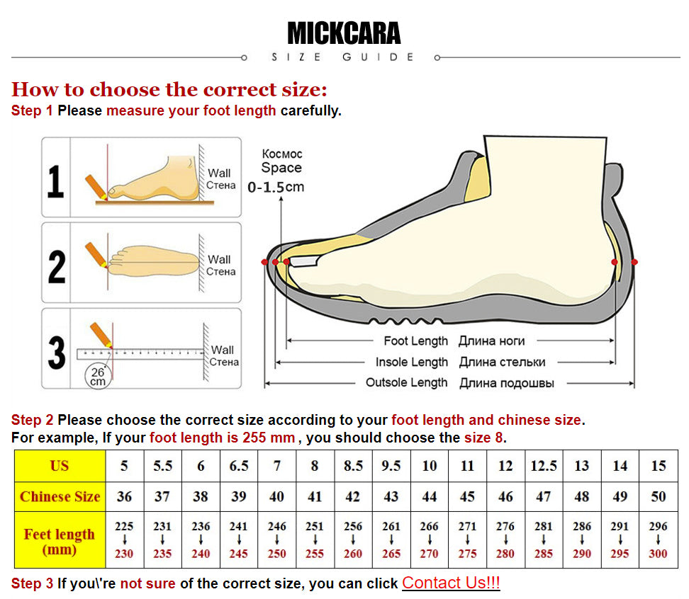
How to choose the correct size:
Step 1 Please measure your foot length carefully.

Step 2 Please choose the correct size according to your foot length and chinese size.
For example, If your foot length is 255 mm , you should choose the size 8.